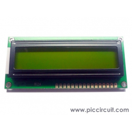
This tutorial shows how to use iCP05 iBoard Lite, 2x16 LCD and a serial RC circuit as an OhmMeter. *Support is NOT provided for this tutorial.
Coding Explanation:
- Define the Measure Pin (RA0) and Current Pin (RA1)
#define OHMMETER_MEASURE_PIN 0b0000
#define OHMMETER_CURRENT_PIN RA1
- We use the charging an discharging time of a serial RC circuit to measure the resistor with a fixed capacitor. The current is provided to the resistor through OHMMETER_CURRENT_PIN and the voltage is taken at the capacitor through OHMMETER_MEASURE_PIN.
Struct
{
unsigned Offset :4;
unsigned Sample :1;
unsigned OverRange :1;
unsigned UnderRange :1;
unsigned Error :1;
} OhmMeter_Status;
- The OhmMeter_Status structure is one byte in size and is used to control the behavior of the OhmMeter.
- With bigger resistor values, it might happen that the capacitor will not completely charge nor completely discharge and the ADC will read 1 or 2 instead of 0 and 253 or 254 instead of 255 for instance. If the timer overflows, i.e. the capacitor does not reach 0 or 255, then ‘Offset’ is incremented and the time measuring is stopped when the ADC reads Offset or 255-Offset. Finally, the #define OHMMETER_TIMELIMIT 3 makes sure that after several overflow the OhmMeter will report an error using the ‘Error’ bit.
- The ‘Sample’ bit is used to know if the timer overflow happens while the resistor was being measured or not. During the measure, when the timer overflows, the ‘Offset’ value is incremented, if not, ‘- ------‘ is displayed on the LCD.
- The ‘OverRange’ and ‘UnderRange’ bits depend on the average charging / discharging time, with a 16F722 20MHz, one needs about 0xA4 for the 4 charges and 4 discharges (i.e. a minimum resistor value of about 325 Ohms) so around this value or a bit less the UnderRange flag is used and a '<' is displayed before the measured resistor value. The ‘OverRange’ flag is used for an overall time value of 0xC000. These values are of course dependent on the fixed capacitor value and can be readjusted, especially if one uses several capacitors for several measuring ranges.
void OhmMeter_Init()
{
ADCON0 = (OHMMETER_MEASURE_PIN << 2) | 0b00000001;
ADCON1 = 0b00100000;
T1CON = 0b00110100;
}
- The OhmMeter_Init() function sets up the ADC (ADCON0 and ADCON1) as well as the timer T1CON.
- The OhmMeter_Measure() function starts by a single discharge of the capacitor before starting a cycle of 4 charges and discharges, so that ADCMean = 8 x t = 8 x R.C with C = 100nF = 10e-7F, i.e.
R = ADCMean / (10e-7 * 8)
- ADCMean measures a number of cycles of the timer frequency, so that, in the end, with the chosen values for C and the timer
R = ADCMean x 2

- In the final version, one can also take into account that the value of the capacitor is not exactly 100nF by measuring some precisely known resistor values. In my case, with my capacitor, I can multiply by 2055 and divide by 1024 (i.e. >> 10). In which case, it is possible to display the ADCMean value with the resistor value by adding the following line of code:
LCDDriver_DisplayVar(1, 3, (void *) &ADCMean, ‘l’, ‘h’);
- One can see that for most of the resistor values between 325 and 100k the ADCMean value is quite stable. Outside this range the value of the capacitor needs to be modified.
- To go below 325 Ohms resistors, one would have to use smaller capacitor values. To go more than 100kOhm (approximately) one would have to use bigger capacitor values.
Remarks:
- The precision of the measurement depends on the exact value of the capacitor
Download:
Special Thanks to: Phi2 for providing the coding and information.