usbStick is built with a simple set of external ports connection that fulfilled any type connector. With these IO ports, user can easily plug in different type of IO modules with direct conntection to USB port.
* NEW iCP12 in Arduino Form (iCP12A - DAQduino): Link
The features of iCP12B are listed as followings:
- Mini size, easy interfacing, high performance and user friendly device
- Used with PIC18F2553 28-Pin Flash USB PIC MCU
- Excellent flexibility that allows user to expand the board with plug and play modules
Peripheral Features:
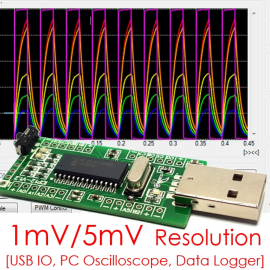
- 12x IO Port (5x 12bit/1mV ADC pins, 2x 10 bit PWM/Freq/DAC pins)
- 4.096V Precision Shunt voltage reference at A3 pin
- Micro USB connector with Serial port emulation (UART Baud Rates: 300 bps to 115.2 kbps)
- Supported operating systems (32bit/64bit): Windows XP ,Windows Vista, Windows 7, Windows 8, Windows 10, Linux, Mac OS X and Raspberry Pi
- Maximum Voltage: 5Vdc
- 100mA current output at VDD pin with over-current protection
- 20MHz oscillator
- Green LED - power on indicator
- 2x LEDs (Green, Red) - status indicator
- ICSP Connector - on-board PIC programming
- Switch Mode Selection - Boot or Normal mode
SmartDAQ v1.4 Features:
- Sampling channel: 5x Analogs (12 bit ADC) + 7x Digitals (Input/Output)
- PIC18F2553 [12bit ADC: 1mV Resolution]
- Maximum Sampling rate: 1KHz or 1mSec/Samples
- Sampling voltage: 0V - 5V (auto & scalable graph) at 1mV Res. Dispaly
- Sampling period:
- mSec: 1, 2, 5, 10, 20, 50, 100, 200, 500
- Sec: 1, 2, 5, 10, 20, 30
- Min: 1, 2, 5, 10, 20, 30, 60
- Trigger Mode: Larger [>], Smaller [<], Positive edge [↑], Negative edge [↓]
- Sampling Mode: Continuous, Single
- VDD or External Vref Input Mode
- Logging Function:
- Save Format: Text, Graphic, Both
- Start Time: Normal, Once Trigger, 24-Hour Clock (Auto Run)
- End Time: Unlimited, Data Size, 24-Hour Clock (Auto Stop)
Dimension:
- Dimension: 7.0cm X 2.3cm X 0.5cm (H)
- Standard 1x5 2.54mm Pin Socket for ICSP connection
- Standard 4x6 2.54mm Pin Socket for IO Port connection
Remarks:
- Overvoltage or overcurrent may damage the MCU. Extended exposure to stresses above the Recommended Operating Conditions may affect device reliability.
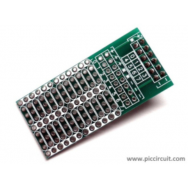
Layout:

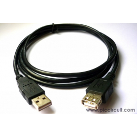
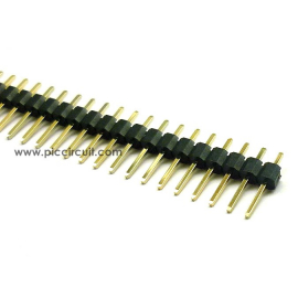
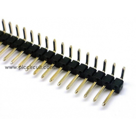
Accessories List: (These accessories would be shipped together)
- 28 Pin PIC: PIC18F2553
- Preloaded Firmware: HID Bootloader + iCP12 DAQv1.4 Firmware
- iCP12 firmware can be updated using Microchip USB HID Bootloader via USB port
- NO programmer is required!
Firmware Upgrade:
- First, switch the SW1 to 'A' for bootloader mode and connect it to USB port
- Then program the iCP12 with provided firmware (iCP12_xx_Firmware.hex) file
- Disconnect the iCP12 and switch back the SW1 to 'B' for normal operation
Photos:
")
- 3.0V battery measurement with Vref Off/On Comparison [improve the signal accuracy]
")
")
- All 6x ADC signals overlap together into a single line: x1, x2, x5, x10 (Zoom Scale)
")
")
")
")
- Parallel Recording in 'Text & Graphic Form' at 1mSec Sample Rate (0.5 sec/graph)
")

")
")
Video:
Download:
- iCP12Bv1.0 usbStick: Schematic
- iCP12B SmartDAQ Firmware: v1.4 [New]
- iCP12 Software Pack v1.4 (Serial Driver, Bootloader, Firmware, SmartDAQ v1.4...): zip
- HID firmware, ioControl Demo PIC Source Code: contact us
- FREE Visual Basic 2008 Express Software: Link
- PIC18F2550 Datasheet: pdf
- PIC18F2553 Datasheet: pdf
- MPLAB IDE 8.40 (93.7MB): zip
Android Apps:
")
Software:
- Software 01 - ioControl: Link
- Software 02 - SerialComm: Link
- Software 03 - SmartDAQ: Link
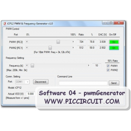
- Software 04 - pwmGenerator: Link
- Software 05 - adcStream: Link
Third-Party Software:
- TestiCP12 interface (animations control): Link
- iCP12 IO Control for the Raspberry PI (by CWRoos): Link
- Tool for Linux and Mac OS X to support iCP12: Link
Product Reviews::
- Embedded Lab - iCP12 usbStick, SmartDAQ and Easy Pulse Sensor: Link
Source Code: FREE ioControl source code (VB2008)
- Download link will be provided immediately after payment
- Please download the file at [My Account][My orders][Order details][Reference]

 - usbStick (Micro USB DAQ, PC Oscilloscope, Data Logger, Frequency Generator, PIC18F2553 IO Board)")
 - usbStick (Micro USB DAQ, PC Oscilloscope, Data Logger, Frequency Generator, PIC18F2553 IO Board)")

 - usbStick (Micro USB DAQ, PC Oscilloscope, Data Logger, Frequency Generator, PIC18F2553 IO Board)")
 - usbStick (Micro USB DAQ, PC Oscilloscope, Data Logger, Frequency Generator, PIC18F2553 IO Board)")